This modification will allow low speed fan operation at a lower than stock temperature,
without setting any codes.
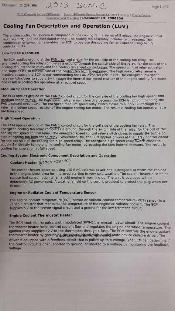
This is a 3-speed fan, with two resistors built into the fan motor itself, to limit motor current on the two lower speeds.
There are a total of five fan control relays.
Three primary relays in the fuse/relay box, and two secondary relays, mounted on the driver side of the radiator support, all by themselves.
These two relays are where you want to tap in at.
You can wire in an "override" circuit to trigger the low speed circuit without triggering any PCM codes.
The wire you are after is Lt. Green, with violet stripe. It goes to both relays, so it doesn't matter which relay you uncover the wiring to, they are on the same circuit.
Tapping into this wire to a manual switch and/or thermostatic switch will allow you to trigger the low speed circuit without triggering any codes.
I just trimmed a spade terminal that I pushed into the socket terminal under the relay.
Didn't have to even splice into the wire itself.
One thing to note is, that when this override is engaged, the fan basically becomes just a two-speed unit, low and high speeds only.
If the override circuit is engaged, and the PCM commands a medium fan speed, high speed will result.
If the override circuit is not engaged, the fan will operate in its normal 3-speed configuration.
I bought a small thermal switch with a 160 deg. on, 145 deg. off setting, and glued it to the radiator core.
Basically, one side of the switch taps into the lt. green/violet wire, the other side to chassis ground.
Now just because the fan switch I used turns on at 160° does not mean the engine will operate at 160, just that the outlet side of the radiator will likely not exceed 160 by much.
The engine operating temperature will still be governed by the coolant thermostat.
The peak temperature may drop by about ~7° when stopped, or in stop-n-go traffic.
A manual switch could also be tapped into this same circuit.
Heres a diagram of the cooling fan circuit:
I added the arrows to indicate current flow, from positive to negative.
In the upper right corner of the diagram, you can see where I marked in the modification.
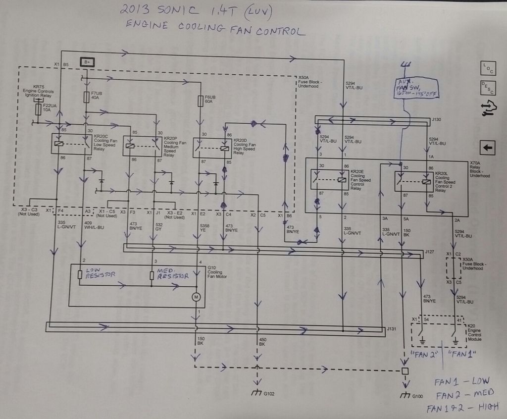
Keep in mind this is for a 2013 1.4T model, so I can't guarantee it is correct for the 1.8L or other model years, but I suspect it may work for others as well. Just not certain of it...
without setting any codes.
This is a 3-speed fan, with two resistors built into the fan motor itself, to limit motor current on the two lower speeds.
There are a total of five fan control relays.
Three primary relays in the fuse/relay box, and two secondary relays, mounted on the driver side of the radiator support, all by themselves.
These two relays are where you want to tap in at.
You can wire in an "override" circuit to trigger the low speed circuit without triggering any PCM codes.
The wire you are after is Lt. Green, with violet stripe. It goes to both relays, so it doesn't matter which relay you uncover the wiring to, they are on the same circuit.
Tapping into this wire to a manual switch and/or thermostatic switch will allow you to trigger the low speed circuit without triggering any codes.
I just trimmed a spade terminal that I pushed into the socket terminal under the relay.
Didn't have to even splice into the wire itself.
One thing to note is, that when this override is engaged, the fan basically becomes just a two-speed unit, low and high speeds only.
If the override circuit is engaged, and the PCM commands a medium fan speed, high speed will result.
If the override circuit is not engaged, the fan will operate in its normal 3-speed configuration.
I bought a small thermal switch with a 160 deg. on, 145 deg. off setting, and glued it to the radiator core.
Basically, one side of the switch taps into the lt. green/violet wire, the other side to chassis ground.
Now just because the fan switch I used turns on at 160° does not mean the engine will operate at 160, just that the outlet side of the radiator will likely not exceed 160 by much.
The engine operating temperature will still be governed by the coolant thermostat.
The peak temperature may drop by about ~7° when stopped, or in stop-n-go traffic.
A manual switch could also be tapped into this same circuit.
Heres a diagram of the cooling fan circuit:
I added the arrows to indicate current flow, from positive to negative.
In the upper right corner of the diagram, you can see where I marked in the modification.


Keep in mind this is for a 2013 1.4T model, so I can't guarantee it is correct for the 1.8L or other model years, but I suspect it may work for others as well. Just not certain of it...
Last edited:
