fiddlerboy
New member
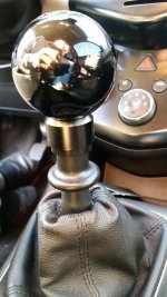
I bought a 2012 Sonic LTZ 1.4 M6 this summer. 110k miles, and the cover of the shifter was missing at the dealership; the knob was there, it was just pointy plastic parts that the labeled and padded cover was supposed to engage with. I wrapped it in duct tape so the plastic bits wouldn't jab my hand every shift. Having a poke-y shifter is a way to ensure you don't rest your hand there, I guess!
I think I found all of the threads here where people discussed replacing their disintegrating manual shift knobs, but none of them quite had all the details. So, here are some photos and comments for anyone else looking to do this. Machinists won't be surprised by any of this, but I learned quite a bit along the way.
I bought the following from Sickspeed, totaling about $60.
That last adapter/reducer was bought after a consult with my friend where he suggested we'd have a lot easier time of it threading this 0.5" rod to 1/2-20 instead of cutting off ~2mm to be able to thread it to 10-1.25. This required modifying the reverse lockout too.
After asking at a couple of auto shops and getting turned-down for the job (I learned why they weren't interested: it's a pain), I found a friend who is a master machinist and was bored. I'm glad I didn't try to go it alone: I would have had a devil of a time cutting and threading this to 10x1.25! I've seen people on the forums who said they did that, and I'm very curious how they managed to shave off that much material.
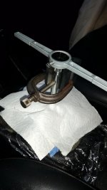
My recommendation for anyone who wants to do this with less trouble is to ask Sickspeed if they can make a 1/2-20 reverse adapter with the same inner diameter as their 10-1.25 one (linked above). We ended up drilling out the reverse adapter and re-tapping it to 1/2-20. To do that without maring the outer surface required my friend making a custom clamp for the inner surface to hold it tight in his small lathe while drilling and tapping. In the end it required over-drilling slightly because the tap was binding. It's totally functional, but that was an extra 20-30 minutes to get it carefully re-drilled by someone with a very experienced hand at this sort of thing.
All of the clever ideas (like how to protect the space under the boot) below are from my friend, not me.
Some photos to document the process:

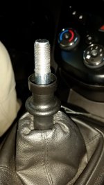
This is what the shift lever looks like after you pull off the knob. On my 2012 6-speed, it just took some twisting back and forth with my hand and a strong grip to remove the knob. There is no set screw. You can then remove the reverse lockout and boot by lifting it up and shimmying it a bit at the top and bottom. Removing the lockout and boot makes for a lot easier working space.
Once you've done that, you've got the whole shift lever exposed. Don't drop anything down there! Since it's now time to cut metal, we want to protect that space.

Slide a sheet of plastic wrap down over the shifter, poking a small hole in the top so it's a very tight fit. This covers the hole that the boot covered and is your "last resort" protection. Use painter's tape with the sticky-side up to form a protective layer above this to catch the metal shavings. We had a grid of tape poked through the rod, plus extra on the sides, and then a cone-shaped piece as an extra "inner" protection at the top. You really don't want sharp metal shavings falling into the mechanism.
In order to help the die engage better, I filed off a few thousandths around the knob, taking off most of the knurling. You can see the beginnings of that process in the photo above, including the bits of metal from the filing caught on the tape. File North/South then East/West, then the diagonals, then round it off. A locking micrometer ensured we got it narrowed enough in each direction. This helped the die engage to start cutting: a 1/2-20 die really wants slightly less than a 0.5" diameter rod.

When it's time to start threading, push a couple of paper towels down over the rod, to catch any drippings from the cutting oil. This will also catch the metal shavings, but you've still got the tape and plastic wrap for protection underneath.
My friend used a v-block clamped to the rod to ensure the die threaded on straight. I let him do this part: he had a good feel for when it was engaging properly.

Once it's engaged, you have the slow process of turning it a half to full turn, then backing off, then adding some cutting fluid, etc. It was very tight and slow going. The die was a cheap one from a set and my friend wasn't that concerned or surprised when it cracked during use. A better die might have made this easier.

This is part way through the cutting process: you can see the shiny metal bits from the threading. In the end, we went a bit over an inch down. I did the final cutting myself at home, once we verified everything fit together ok. In order to get the new knob to not stick up too high compared with the original equipment, you have to thread down past the knurled part. At first we just went to where the knurling ends, but there the knob stuck up noticeably higher and there was a lot of the lockout shaft still visible. The thickness of the reverse adapter adds a noticeable bit of height compared with the original integrated knob.
Photos of the finished job will go in the next post.
I think I found all of the threads here where people discussed replacing their disintegrating manual shift knobs, but none of them quite had all the details. So, here are some photos and comments for anyone else looking to do this. Machinists won't be surprised by any of this, but I learned quite a bit along the way.
I bought the following from Sickspeed, totaling about $60.
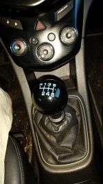
- BLACK ENGRAVED SHIFT KNOB 6RUL 10X1.25
- REVERSE LOCK-OUT SHIFT KNOB ADAPTER 10X1.25
- SICKSPEED SHIFT KNOB ADAPTOR STANDARD THREAD JAM NUT AND REDUCER 1/2-20
That last adapter/reducer was bought after a consult with my friend where he suggested we'd have a lot easier time of it threading this 0.5" rod to 1/2-20 instead of cutting off ~2mm to be able to thread it to 10-1.25. This required modifying the reverse lockout too.
After asking at a couple of auto shops and getting turned-down for the job (I learned why they weren't interested: it's a pain), I found a friend who is a master machinist and was bored. I'm glad I didn't try to go it alone: I would have had a devil of a time cutting and threading this to 10x1.25! I've seen people on the forums who said they did that, and I'm very curious how they managed to shave off that much material.
My recommendation for anyone who wants to do this with less trouble is to ask Sickspeed if they can make a 1/2-20 reverse adapter with the same inner diameter as their 10-1.25 one (linked above). We ended up drilling out the reverse adapter and re-tapping it to 1/2-20. To do that without maring the outer surface required my friend making a custom clamp for the inner surface to hold it tight in his small lathe while drilling and tapping. In the end it required over-drilling slightly because the tap was binding. It's totally functional, but that was an extra 20-30 minutes to get it carefully re-drilled by someone with a very experienced hand at this sort of thing.
All of the clever ideas (like how to protect the space under the boot) below are from my friend, not me.
Some photos to document the process:

This is what the shift lever looks like after you pull off the knob. On my 2012 6-speed, it just took some twisting back and forth with my hand and a strong grip to remove the knob. There is no set screw. You can then remove the reverse lockout and boot by lifting it up and shimmying it a bit at the top and bottom. Removing the lockout and boot makes for a lot easier working space.
Once you've done that, you've got the whole shift lever exposed. Don't drop anything down there! Since it's now time to cut metal, we want to protect that space.

Slide a sheet of plastic wrap down over the shifter, poking a small hole in the top so it's a very tight fit. This covers the hole that the boot covered and is your "last resort" protection. Use painter's tape with the sticky-side up to form a protective layer above this to catch the metal shavings. We had a grid of tape poked through the rod, plus extra on the sides, and then a cone-shaped piece as an extra "inner" protection at the top. You really don't want sharp metal shavings falling into the mechanism.
In order to help the die engage better, I filed off a few thousandths around the knob, taking off most of the knurling. You can see the beginnings of that process in the photo above, including the bits of metal from the filing caught on the tape. File North/South then East/West, then the diagonals, then round it off. A locking micrometer ensured we got it narrowed enough in each direction. This helped the die engage to start cutting: a 1/2-20 die really wants slightly less than a 0.5" diameter rod.

When it's time to start threading, push a couple of paper towels down over the rod, to catch any drippings from the cutting oil. This will also catch the metal shavings, but you've still got the tape and plastic wrap for protection underneath.
My friend used a v-block clamped to the rod to ensure the die threaded on straight. I let him do this part: he had a good feel for when it was engaging properly.

Once it's engaged, you have the slow process of turning it a half to full turn, then backing off, then adding some cutting fluid, etc. It was very tight and slow going. The die was a cheap one from a set and my friend wasn't that concerned or surprised when it cracked during use. A better die might have made this easier.

This is part way through the cutting process: you can see the shiny metal bits from the threading. In the end, we went a bit over an inch down. I did the final cutting myself at home, once we verified everything fit together ok. In order to get the new knob to not stick up too high compared with the original equipment, you have to thread down past the knurled part. At first we just went to where the knurling ends, but there the knob stuck up noticeably higher and there was a lot of the lockout shaft still visible. The thickness of the reverse adapter adds a noticeable bit of height compared with the original integrated knob.
Photos of the finished job will go in the next post.


