EX331
Member
Preface
So you want to change your mirror? I can't say that I blame you, as there are some pretty neat options for our Sonics. Though they aren't factory options, they are possible to install.
I hope to have all of my bases covered in these instructions. The instructions that are to follow are believed to be correct based on my experience, there are no warranties expressed or implied for their completeness or accuracy, accordingly I cannot be held liable for errors or damages of any kind. These instructions also assume that your vehicle is of the North American specification, and is equipped with factory OnStar, RPO code UE1.
This article will have the instructions for both frameless and otherwise. The variation will be in the wiring, as the auto-dim uses a keyed 12 volt supply and the frameless uses that, as well as low-speed GMLAN data to operate. Installation is more or less the same.
I will be referring to the mirrors by their RPO Codes;
DBX - Frameless, from the Camaro
DD8 - Auto-dimming, sourced from the Cruze or similar.
Supplies
1) MIRROR x1
First you'll need the mirror, either the standard auto-dimming (DD8), or the frameless (DBX). This goes without saying, but deals can be had on eBay and other places on the internet. Be savvy, and save some money.
2) TERMINATED LEAD/WIRE x1 or 2
GM Part 13575866 is the terminated lead that inserts into the harness that goes to the mirror. It has the terminal, and a section of white wire, and comes with a crimp sleeve to join the wire. You will need two for both kinds of mirror, but you can get by with just one for the DD8 mirror.
3) WIRE TAP x1
I used the Bussmann BP/HHH ATM Add-A-Fuse. Comes with crimp sleeve at the end, already attached to the wire. Here's the item on Amazon, link here, but you can usually obtain them at your local auto parts store.
4) 5 AMP FUSE
5) WIRE
DD8, DBX - 20AWG, red. Enough to reach from the mirror harness to the fuse block area where you will insert the fuse tap.
DD8 - 20AWG, white. This is optional, enough to run from mirror to wherever you can get ahold of to tap the backup lamp supply voltage. Personally, I skipped this.
DBX - 20AWG, green. Enough to reach from the mirror to where you opt to connect to the low speed GMLAN. I used the OBD connector at the driver's footwell.
6) SMALL ZIP TIES
Used for routing the wire down the "A" pillar along the existing wire harness. Crucial, as you do not want the wires obstructing the side airbag.
7) ELECTRICAL TAPE
Recommended. To cover and/or secure installed wiring.
8) WIRE MOLDING
Optional. I used this to keep the wire contained as it went down the "A" pillar, and into the dashboard.
Tools
• Wire crimp/strip tool
• Driver with appropriate torx and phillips bits
• Tool for pulling wire (not sure what it's called, but it's helpful)
• Flashlight
Procedure - Go to the next step unless otherwise indicated. Vehicle is off, key removed from ignition;
1) Remove the shrouds at the base of the mirror by pulling away from the center of the windshield.
2) Loosen the screw securing the mirror to the windshield with your torx driver, and lift the mirror off the mounting hardware.
3) Disconnect the mirror from the wiring harness. Press inward on locking tab and separate. I used the end of the torx for this.
4) Remove "A" pillar trim. Pull on upward section until it comes apart (Fig. 4A). You will then have to disconnect the trim piece from the black "springy" retainer that is used to keep the trim in place in the event of side airbag deployment (Fig. 4B). If equipped, disconnect the wiring going to the tweeter at the base of the trim piece. The tab is large enough to easily pinch with your fingers (Fig. 4C).
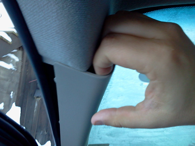
Figure 4A
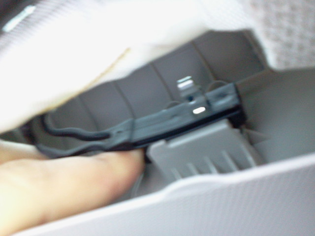
Figure 4B
5) Remove dash panel beneath the steering column. I believe it took 6 phillips screws to do this. Be mindful of one retaining clip in the smallest section that is adjacent to the center console. You will also, in doing this, have to disconnect the exterior light control switch from the harness. If you do not wish to do that, simply remove the access panel for the fuse panel. It is my opinion that removing the whole panel will make your life a whole lot easier, as it gives you more room to work.
6) Remove the OBD connector, by pressing a tab at the top of the connector and pulling the connector downward.
At this point, you're ready to start running wire.
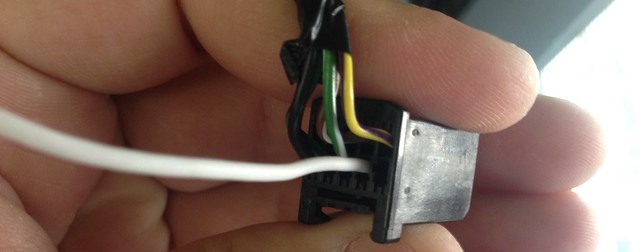
For connector reference - the white wire is inserted in pin 2 in this photo
7) Insert terminated leads into rear view mirror harness connector. You will see very small numbers that will help you identify the terminals near to the socket where the terminated leads will be inserted.
DD8 mirror, go to step 8. DBX mirror, go to step 11.
8) DD8 Mirror terminals: Insert terminated leads into the following pins;
9) DD8 - Connect your red wire to Pin 2 by way of crimp connector, and if you opted to do so, white wire to pin 1 using the same method. Go to step 10
10) DD8 - Optional. Route white wire to back up lamp voltage supply location. Could be either rear tail lamp, or somewhere on the BCM. Personally, I didn't bother. Route red wire as described in step 13. Go to step 13.
11) DBX Mirror terminals: Insert terminated leads into the following pins;
12) DBX - Connect your green wire to pin 1 by way of crimp connector. Connect your red wire to pin 10 using the same method. Route green wire along with red wire in step 13. Go to step 13.
13) Route wiring. Tuck underneath headliner at the top of windshield between the rear view mirror and "A" pillar, making sure to leave enough slack so that there is no undue strain on the wires, both new and existing. At the edge of the headliner tuck the wire(s) up under the corner of the headliner. Now, run wire(s) along the existing wiring harness until approximately 1 to 3 inches below the anchor for the side airbags. Install a small zip tie at this location, as well as a few places between there and the headliner to ensure the wire(s) remain securely in place. Trim away excessive length from zip ties. Be vigilant to ensure that the path of the side airbag is not obstructed in any way. Now, draw the wire into the dashboard near to the fuse block area. A tool for doing this would be helpful.
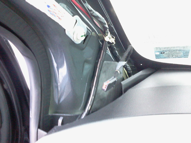
Figure 13 - Intended path of wires near base of "A" pillar
14) Attach Bussmann BP/HHH ATM Add-A-Fuse to the end of the red wire by way of crimp connector. Install 5A fuse in the slot closest to the red wire on the BP/HHH.
15) Remove 10A fuse from #40 in the cabin fuse block. This is a "spare" fuse that is only on with the key in the run position. Insert that fuse into the other slot on the Bussmann BP/HHH ATM Add-A-Fuse.
16) Install the Bussmann BP/HHH ATM Add-A-Fuse into #40 of the cabin fuse block, with the fuses pointing upward and the red wire pointing to the left. DBX go to step 17, DD8 go to step 19.
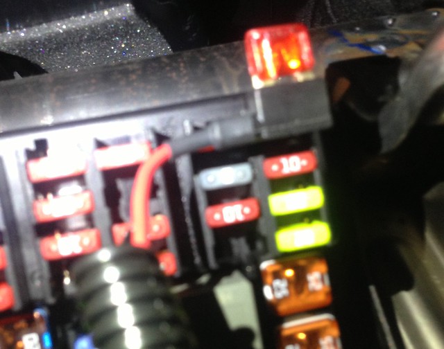
Figure 16 - BP/HHH installed
17) DBX - Install GMLAN wire. Because I did not feel comfortable piercing the GMLAN wiring, I chose to insert the wire into the back of the OBD connector. I stripped just enough off the green wire so that I was able to insert it into the back of the connector with no bare wire exposed. Connect to pin 1 of the OBD connector, the wire going to pin 1 of the OBD connector is also green.
18) DBX - Wrap green wire with electrical tape so that it is not exposed, and it would ensure the wire remains seated in the back of the connector. Go to step 19.
19) Install mirror. Insert wire harness into the connector for the rear view mirror, then install mirror on mounting hardware.
20) Testing. Insert the key and turn it to the run position. DD8 go to step 21. DBX go to 22.
21) DD8 - Place your finger over the sensor on the side of the mirror that faces traffic, and shine your flashlight into the oval space at the top of the mirror glass. This should cause your mirror to tint, and is functioning normally. Your OnStar buttons LED will function business as usual. If the mirror doesn't dim, check to ensure your connections are good, and wire crimps are done correctly. Go to step 23.
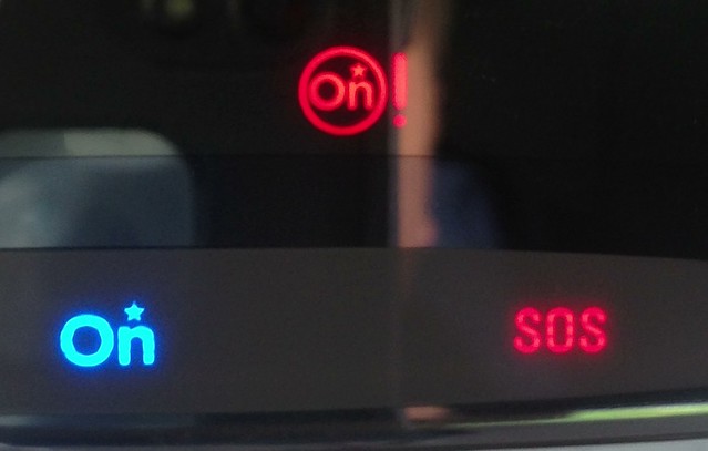
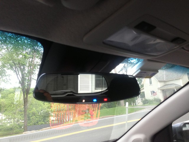
22) DBX - You should see the OnStar function buttons glowing. If not, check to ensure your connections are good, and wire crimps are done correctly. If they do, start your vehicle. Place your finger over the sensor on the side of the mirror that faces traffic, and shine your flashlight in the area above, and to the right of, the voice command button. Your mirror will dim. See notes that follow. Go to step 23.
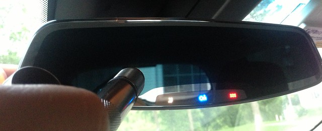
Figure 22 - Testing DBX Mirror
23) Reinstall interior trim by following steps 6 through 1 in reverse.
So you want to change your mirror? I can't say that I blame you, as there are some pretty neat options for our Sonics. Though they aren't factory options, they are possible to install.
I hope to have all of my bases covered in these instructions. The instructions that are to follow are believed to be correct based on my experience, there are no warranties expressed or implied for their completeness or accuracy, accordingly I cannot be held liable for errors or damages of any kind. These instructions also assume that your vehicle is of the North American specification, and is equipped with factory OnStar, RPO code UE1.
This article will have the instructions for both frameless and otherwise. The variation will be in the wiring, as the auto-dim uses a keyed 12 volt supply and the frameless uses that, as well as low-speed GMLAN data to operate. Installation is more or less the same.
I will be referring to the mirrors by their RPO Codes;
DBX - Frameless, from the Camaro
DD8 - Auto-dimming, sourced from the Cruze or similar.
Supplies
1) MIRROR x1
First you'll need the mirror, either the standard auto-dimming (DD8), or the frameless (DBX). This goes without saying, but deals can be had on eBay and other places on the internet. Be savvy, and save some money.
2) TERMINATED LEAD/WIRE x1 or 2
GM Part 13575866 is the terminated lead that inserts into the harness that goes to the mirror. It has the terminal, and a section of white wire, and comes with a crimp sleeve to join the wire. You will need two for both kinds of mirror, but you can get by with just one for the DD8 mirror.
3) WIRE TAP x1
I used the Bussmann BP/HHH ATM Add-A-Fuse. Comes with crimp sleeve at the end, already attached to the wire. Here's the item on Amazon, link here, but you can usually obtain them at your local auto parts store.
4) 5 AMP FUSE
5) WIRE
DD8, DBX - 20AWG, red. Enough to reach from the mirror harness to the fuse block area where you will insert the fuse tap.
DD8 - 20AWG, white. This is optional, enough to run from mirror to wherever you can get ahold of to tap the backup lamp supply voltage. Personally, I skipped this.
DBX - 20AWG, green. Enough to reach from the mirror to where you opt to connect to the low speed GMLAN. I used the OBD connector at the driver's footwell.
6) SMALL ZIP TIES
Used for routing the wire down the "A" pillar along the existing wire harness. Crucial, as you do not want the wires obstructing the side airbag.
7) ELECTRICAL TAPE
Recommended. To cover and/or secure installed wiring.
8) WIRE MOLDING
Optional. I used this to keep the wire contained as it went down the "A" pillar, and into the dashboard.
Tools
• Wire crimp/strip tool
• Driver with appropriate torx and phillips bits
• Tool for pulling wire (not sure what it's called, but it's helpful)
• Flashlight
Procedure - Go to the next step unless otherwise indicated. Vehicle is off, key removed from ignition;
1) Remove the shrouds at the base of the mirror by pulling away from the center of the windshield.
2) Loosen the screw securing the mirror to the windshield with your torx driver, and lift the mirror off the mounting hardware.
3) Disconnect the mirror from the wiring harness. Press inward on locking tab and separate. I used the end of the torx for this.
4) Remove "A" pillar trim. Pull on upward section until it comes apart (Fig. 4A). You will then have to disconnect the trim piece from the black "springy" retainer that is used to keep the trim in place in the event of side airbag deployment (Fig. 4B). If equipped, disconnect the wiring going to the tweeter at the base of the trim piece. The tab is large enough to easily pinch with your fingers (Fig. 4C).
Figure 4A
Figure 4B
5) Remove dash panel beneath the steering column. I believe it took 6 phillips screws to do this. Be mindful of one retaining clip in the smallest section that is adjacent to the center console. You will also, in doing this, have to disconnect the exterior light control switch from the harness. If you do not wish to do that, simply remove the access panel for the fuse panel. It is my opinion that removing the whole panel will make your life a whole lot easier, as it gives you more room to work.
6) Remove the OBD connector, by pressing a tab at the top of the connector and pulling the connector downward.
At this point, you're ready to start running wire.
For connector reference - the white wire is inserted in pin 2 in this photo
7) Insert terminated leads into rear view mirror harness connector. You will see very small numbers that will help you identify the terminals near to the socket where the terminated leads will be inserted.
DD8 mirror, go to step 8. DBX mirror, go to step 11.
8) DD8 Mirror terminals: Insert terminated leads into the following pins;
Pin 1 - This is your backup lamp supply voltage. Optional. When voltage is applied here the auto dim function is defeated. Wiring this in to your reverse lighting will defeat the auto dim function when your vehicle is put in reverse.
Pin 2 - 12 volt supply, keyed. This supplies the voltage to the auto-dimming circuitry, necessary for it to function. Go to step 9.
9) DD8 - Connect your red wire to Pin 2 by way of crimp connector, and if you opted to do so, white wire to pin 1 using the same method. Go to step 10
10) DD8 - Optional. Route white wire to back up lamp voltage supply location. Could be either rear tail lamp, or somewhere on the BCM. Personally, I didn't bother. Route red wire as described in step 13. Go to step 13.
11) DBX Mirror terminals: Insert terminated leads into the following pins;
Pin 1 - Low Speed GMLAN. This supplies the data necessary for the mirror to function.
Pin 10 - 12 volt supply, keyed. This supplies the voltage to mirror's logic circuitry, necessary for it to function. Go to step 12.
12) DBX - Connect your green wire to pin 1 by way of crimp connector. Connect your red wire to pin 10 using the same method. Route green wire along with red wire in step 13. Go to step 13.
13) Route wiring. Tuck underneath headliner at the top of windshield between the rear view mirror and "A" pillar, making sure to leave enough slack so that there is no undue strain on the wires, both new and existing. At the edge of the headliner tuck the wire(s) up under the corner of the headliner. Now, run wire(s) along the existing wiring harness until approximately 1 to 3 inches below the anchor for the side airbags. Install a small zip tie at this location, as well as a few places between there and the headliner to ensure the wire(s) remain securely in place. Trim away excessive length from zip ties. Be vigilant to ensure that the path of the side airbag is not obstructed in any way. Now, draw the wire into the dashboard near to the fuse block area. A tool for doing this would be helpful.
Figure 13 - Intended path of wires near base of "A" pillar
14) Attach Bussmann BP/HHH ATM Add-A-Fuse to the end of the red wire by way of crimp connector. Install 5A fuse in the slot closest to the red wire on the BP/HHH.
15) Remove 10A fuse from #40 in the cabin fuse block. This is a "spare" fuse that is only on with the key in the run position. Insert that fuse into the other slot on the Bussmann BP/HHH ATM Add-A-Fuse.
16) Install the Bussmann BP/HHH ATM Add-A-Fuse into #40 of the cabin fuse block, with the fuses pointing upward and the red wire pointing to the left. DBX go to step 17, DD8 go to step 19.
Figure 16 - BP/HHH installed
17) DBX - Install GMLAN wire. Because I did not feel comfortable piercing the GMLAN wiring, I chose to insert the wire into the back of the OBD connector. I stripped just enough off the green wire so that I was able to insert it into the back of the connector with no bare wire exposed. Connect to pin 1 of the OBD connector, the wire going to pin 1 of the OBD connector is also green.
18) DBX - Wrap green wire with electrical tape so that it is not exposed, and it would ensure the wire remains seated in the back of the connector. Go to step 19.
19) Install mirror. Insert wire harness into the connector for the rear view mirror, then install mirror on mounting hardware.
20) Testing. Insert the key and turn it to the run position. DD8 go to step 21. DBX go to 22.
21) DD8 - Place your finger over the sensor on the side of the mirror that faces traffic, and shine your flashlight into the oval space at the top of the mirror glass. This should cause your mirror to tint, and is functioning normally. Your OnStar buttons LED will function business as usual. If the mirror doesn't dim, check to ensure your connections are good, and wire crimps are done correctly. Go to step 23.
22) DBX - You should see the OnStar function buttons glowing. If not, check to ensure your connections are good, and wire crimps are done correctly. If they do, start your vehicle. Place your finger over the sensor on the side of the mirror that faces traffic, and shine your flashlight in the area above, and to the right of, the voice command button. Your mirror will dim. See notes that follow. Go to step 23.
Figure 22 - Testing DBX Mirror
23) Reinstall interior trim by following steps 6 through 1 in reverse.
Last edited:

 good work